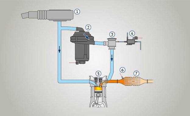
Secondary Air Injection System Diagram. is handy SAS diagram Volvos the "white" block 5-cyl engines, some 1996 all 1997 850 models, S70, XC70 V70 to year 2000, C70 to year 2004. CoryLeeS70 » Volvo community! I've purchased 1998 Volvo S70 (N/A) the cheap I'm a .
 The Secondary Air Injection System (SAIS) part a vehicle's exhaust system. Manufacturers began introducing in 1960s help reduce hydrocarbon carbon monoxide emissions, of resulted incomplete combustion. Toyota Lexus SAIS systems only commanded operate a cold start, is the engine .
 Secondary air injection (commonly as air injection) a vehicle emissions control strategy introduced 1966, . Details diagrams the Chevrolet Camaro AIR system www.camaros.org page last edited 18 April 2024, 10:47 (UTC). Text available the Creative .
 The Secondary Air Injection (AIR) system consists an air pump, Air Switching Valve (ASV), pressure sensor, Air Injection Control Driver (AID) the ECM. . WIRING DIAGRAM. Refer DTC P0412 (See page ). CAUTION / NOTICE / HINT. HINT: Read freeze frame data the Techstream. Freeze frame data records engine condition .
 Download scientific diagram | Schematic diagrams the secondary air injection system (a), definition the flame zone (b) the diagnostic system (c) publication: Attenuation .
 Abstract: Diagram shows the secondary air system components installed the 2.5 liter engine. Applies to: Volkswagen Beetle 1998-2009. . Secondary Air Injection System Assembly Overview Page 2 3 15 - 10 Nm 16 - Intake manifold Ensure seated tightly
 Secondary Air Injection (AIR) pump motor - V101- Ground (GND) point engine compartment, left, open circuit: Electrical Wiring Diagrams, Troubleshooting & Component Locations no malfunctions detected: - Replace Secondary Air Injection (AIR) pump motor -V101-. Secondary Air Injection (AIR) system, checking Page 19 21
 Introduction the Secondary Air Injection System secondary air injection system a crucial component many vehicles, designed reduce emissions the cold start phase the engine. this guide, we'll explore it works, it's important, provide diagrams help understand layout functionality.
 1 - Secondary air injection (AIR) pump motor -V101-Location Fig. 2 , Page 26-54 Removing installing Page 26-77 2 - Secondary air injection (AIR) pump relay -J299-Location Fig. 3 , Page 26-55 3 - Motronic engine control module (ECM) -J220-4 - combination valve secondary air system Location Fig. 4 , Page 26-55 Checking Page 26-79
 secondary air system, to individual component level. additional tools, schematics equipment, emissions devices be tested the Techstream functions. "Utility" tab be as "bi-directional" control test secondary air emissions devices. function chosen a manual test for
.png)
